

The Part That Passed Inspection and Still Failed
A few years back, I got a call from a quality manager at a Tier 1 aerospaces OEM. They'd received a lot of 5,000 laser-drilled nitinol stent struts from a previous supplier. Every incoming inspection report checked out. The digital microscope scan logs were clean. First article inspection signed and filed.
Then the struts went into subassembly, and about 4% of them failed the crimp test. The hole taper angle had drifted from the nominal 1.2° to closer to 2.1° partway through the production run — well outside the ±0.3° window the design required. The supplier had measured the first part, the last part, and a handful in between. They'd never caught the drift because their measurement station sat at the end of the line, not inside the loop.
This is the problem I want to walk through. If you're sourcing laser micromachining and you see "±5µm tolerance, 100% digital inspection" on a capability statement, that phrase by itself tells you almost nothing. Measurement equipment is an input to process control, not evidence that process control exists.
What ±5µm Actually Means on a Capability Statement
When engineers see "±5µm accuracy" in a vendor pitch, the claim usually collapses under two questions: Accurate relative to what? and With what confidence?
Accuracy vs. Precision vs. Repeatability
Accuracy, precision, and repeatability are three different things. A process can be precise (tight scatter) but inaccurate (tight scatter around the wrong mean). It can be accurate on average but not repeatable part-to-part.
Process Capability (Cpk) Basics
The number that matters for production is process capability — specifically Cpk, which measures how well the process output fits inside the tolerance window, accounting for both centering and spread.
For reference, the practical bar looks like this:
Cpk ≥ 1.33 — the minimum for general production work
Cpk ≥ 1.67 — typical requirement for medical implantables and aerospace flight hardware
A vendor quoting ±5µm without a Cpk value is quoting a best-case measurement, not a production capability. (Source: Tier 1 — AIAG MSA Manual, 4th Edition, Chapter I Section C.)
Tolerance Stack-Up for ±5µm Features
On top of that, a ±5µm feature tolerance is built from a stack of contributors:
- Laser beam quality (M² typically <1.3 for micromachining fiber and UV sources, per ISO 11146 definitions) (Source: Tier 1 — ISO 11146-1:2021.)
- Motion stage positioning resolution, usually sub-micron for linear stages used in laser micro cutting and drilling
- Thermal drift of the machine frame over an 8-hour shift
- Fixture repeatability — often the biggest and most underestimated contributor
- Measurement system uncertainty itself
Measurement System Uncertainty (Gage R&R)
That last point matters more than people realize. If your measurement system has a Gage R&R of 25%, you're consuming a quarter of your tolerance band with measurement noise alone. Anything under 10% is good; 10–30% is conditional; above 30% the measurement system is unfit for the tolerance being checked.

So when we say we hold ±5µm on, for example, a laser-drilled hole in 75µm 316L stainless, what that actually means in practice is: documented Cpk of 1.67 or better across a qualification run, Gage R&R under 10%, and a measurement program tied to a specific feature definition — not just a number on a certificate.
What the Closed Loop Actually Looks Like
Here's what happens on a production floor when a ±5µm job is running. I'll walk through it as a loop because that's how it behaves.
Step 1 — In-Process Sampling
We don't measure the first part, wave it through, and check again at the end. For a typical high-volume run, we pull one part in every 25 for dimensional measurement. For aerospace work under ISO 9001, we often run 100% inspection on critical-to-function features — every single part, every feature.
Step 2 — Data Capture
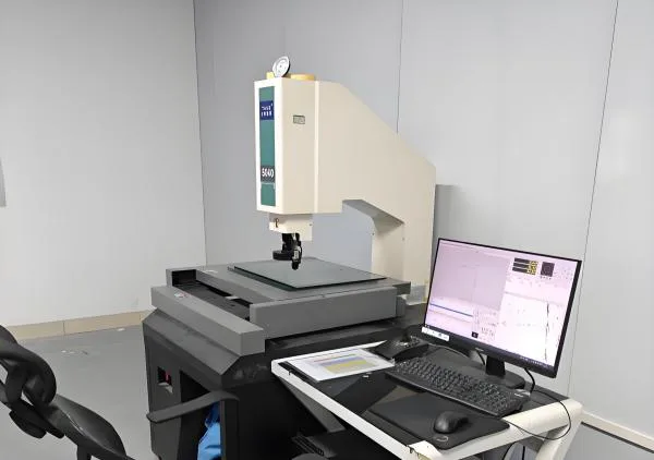
Each sampled part goes onto a measurement station with a canned program. For 2D features — hole diameter, hole position, slot width, edge-to-edge distances — that's typically an image-dimension system, which handles those measurements with instrument uncertainty in the sub-micron range depending on feature size. For edge quality, burr height, and heat-affected zone assessment, we switch to a digital microscope platform. For continuous in-line diameter monitoring on wire-and-tube work, a laser micrometer feeds data directly into the SPC system.
The point isn't which specific instrument model. The point is: the measurement has a defined uncertainty, a validated program, and a data path out of the instrument into something that can act on it.
Step 3 — SPC Trigger Logic
The measurement data doesn't just get logged. It feeds a statistical process control chart with pre-defined reaction rules. The standard rule: if the trailing 10-part moving average drifts past ⅓ of the tolerance band from nominal, the operator gets an alert before any out-of-spec parts have been made. That's the entire point. You don't wait for a reject — you intervene while the process is still inside the window and trending.
Step 4 — Parameter Adjustment
When SPC triggers, the operator has a defined playbook per process. For laser micro drilling, typical corrections are pulse energy trim of ±3%, focus offset adjustment of ±10µm, or galvo beam-path calibration. For laser micro cutting, it's often feed rate trim or assist gas pressure adjustment. These aren't guesses. They're linked to the failure mode that SPC surfaced — taper drift gets a focus correction, diameter drift gets a pulse energy correction.
Step 5 — Verification
After any parameter change, a three-part verification sample confirms the process returned to nominal before production continues. That sample gets logged with the adjustment record. If the process doesn't recover, the job stops and engineering is called in.
That's the loop: measure, evaluate against limits, act, verify. Every one of those steps has a documented procedure, a trained operator, and a data trail. The measurement station is one piece of instrumentation inside a larger system. Without the other four steps, it's an expensive microscope taking pretty pictures.
Why "We Have a Digital Microscope" Isn't the Answer
Most laser micromachining shops have digital microscope equipment somewhere on the floor. The gap between shops isn't the instrument roster — it's what happens around the instruments. Four things separate a real closed loop from theater:

Documented Operator Training & Gage R&R
Every operator running a measurement program has a documented Gage R&R study on file for that program. We know, numerically, how much measurement variation each operator contributes. If one operator's R&R jumps above threshold, that's retraining, not a guessing game. (Source: Tier 1 — AIAG MSA Manual 4th Ed, Chapter III.)
Standardized Measurement Programs
Every feature has a written program. Same edge detection settings, same lighting, same reference datum, every time, every operator. Ad-hoc measurement — "point the microscope at it and eyeball the dimension" — is the single biggest source of false confidence on a shop floor.
Data Traceability Linked to Process Parameters
Every measurement record ties to machine ID, operator ID, material lot, laser parameter set at the time of cut, and a timestamp. When a field issue shows up six months later, we can pull the exact process conditions that made the part. That's the audit trail ISO 13485 Section 7.5.6 expects for any process whose output can't be fully verified by subsequent inspection — which describes most laser micromachining. (Source: Tier 1 — ISO 13485:2016, Section 7.5.6.)
Audit-Ready Documentation as a Byproduct
First article inspection reports per AS9102 and process validation records per ISO 13485 are generated automatically from the data flow. They're not assembled the week before an audit. If you've ever watched a supplier reconstruct inspection records from memory, you know why this matters. (Source: Tier 1 — SAE AS9102 Rev C, 2023.)
That last one is how you tell, in about twenty minutes of a supplier audit, whether the closed loop is real or performative.
Where Digital Microscopy Stops and Other Metrology Starts
A digital microscope is excellent at what it's designed for — 2D dimensional inspection, high-resolution surface imaging, digital microscopy for edge quality. It's not the right tool for every question a laser micromachining job raises. Knowing where one instrument stops and another starts is part of the expertise, and it's a reasonable thing to ask a vendor to explain.
3D Surface Topography & Micron Roughness
For micron surface roughness and 3D topography on laser-structured surfaces, we move to white light interferometry or confocal profilometry. Digital microscopes can estimate surface roughness, but for Sa values under 200nm, interferometry is the honest tool. Research at Fraunhofer ILT on LIPSS (laser-induced periodic surface structures) is built on interferometric characterization for exactly this reason. (Source: Tier 2 — Fraunhofer ILT Annual Report 2023, ultrafast surface structuring section.)

Hidden Internal Geometry Inspection
For hidden geometry — internal taper of deep drilled holes, weld penetration profiles, cross-sectional voids — no optical surface instrument will see it. That requires either destructive metallographic cross-section and SEM imaging, or non-destructive µCT scanning for higher-value parts.
National-Traceable Dimensional Calibration
For true dimensional traceability to national standards, a CMM with a calibrated stylus or optical probe beats any floor microscope. Digital microscopy for production SPC; CMM for first article and gage qualification.
A vendor who claims one instrument does everything either doesn't know where the limits are or is selling you something.
What to Look For in Supplier Documentation
If you're evaluating a laser micromachining supplier and you see "±5µm" on the capability sheet, these are the questions that separate real capability from marketing:
5 Critical Documentation Questions
- What is your documented Cpk for this specific feature at this tolerance, from your most recent qualification run?
- What is your Gage R&R as a percentage of tolerance on the measurement system used to verify this feature?
- What is your in-process sampling rate for production, and what is the written SPC reaction plan when a drift is detected?
- Can you provide an MSA study and a recent AS9102 FAI or ISO 13485 process validation report under NDA?
- How is measurement data linked to the laser parameters and material lot at the time of cut, for traceability?
Any vendor who can answer all five with documentation — not verbal assurance — is running a real closed loop. Any vendor who gets uncomfortable past question two is probably running a measurement station at the end of the line and hoping.
The Bottom Line
Metrology equipment is a necessary condition for holding ±5µm in laser micromachining production. It is not a sufficient one. The difference between a shop that survives an aerospace or medical audit and a shop that doesn't is almost never the instrument list — it's whether measurement data closes back into process parameters with defined rules, trained operators, and an audit trail.
When you see ±5µm on a capability statement, ask what it actually means: Cpk documented, Gage R&R characterized, SPC armed, and traceability intact. The measurement station is part of that. It's not the whole thing.